Friday, 22 December 2023

Grid Couplings


Grid Couplings

Also called teeth couplings, these

 couplings reduce vibration, and compensate for misalignment while transmitting torque. They offer the high torque capacity of a gear coupling and the flexibility of an elastomer coupling, providing a cost-effective solution.

Grid Coupling


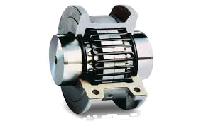
Grid couplings are a type of flexible coupling that can absorb shock, reduce vibration, and compensate for misalignment between two shafts. They have a spring-like grid that spreads out impact energy over time, which reduces the peak loads and protects the machinery. As the load increases, more of the tooth comes into contact with the grid, providing better protection and performance.

Grid Couplings are fully interchangeable between manufacturers. The grid coupling is noted for being simple to install and maintain, reducing downtime.

Contact Chain & Drives to assist in identifying the right grid coupling for your application.

Features & Benefits

  • In the event of severe overload, grid breaks and prevents damage to high capital cost connected equipment.
  • GS Grid Coupling comes with optional Horizontal Split case.
  • When the parallel misalignment is too severe, the relating machine is protected by the virtue of shearing Grid or Tooth.
  • Service life of connected equipment including bearings and seals are extended due to Grid Coupling smooth high torque capabilities.
  • Quick installation and easy maintenance reduce labour cost and downtime costs.
  • GS Grid coupling is interchangeable with international industry standard brands.
  • 100% transmission of power at low noise emission.

Fluid Couplings


Fluid couplings protect your machinery and ensure a longer life for your equipment as

 they comprise of three main elements including the Driving impeller (pump) mounted on the input shaft, the Driven impeller (turbine) mounted on the output shaft and the Cover, flanged to the outer impeller, with an oil-tight seal. The first two elements can work both as pump or turbine.

Used for industrial machine drives, they are a highly efficient as they provide shock-free start-up for the power transmission system, protecting surrounding equipment. Designed to withstand harsh environments and challenging operating conditions.

The fluid couplings are available with delay fill chamber and can be supplied as bare-shaft or fitted with v-belt pulley drives.

Benefits

  • The power transmission is free from vibration and noises
  • Power transmission is smooth even in extreme conditions
  • Shock-free start up
  • Maximum torque can be adjusted by varying the amount of oil filled in the casing
  • Fluid couplings can be used in both vertical and horizontal applications.
  • Overload protection


Stock fewer parts

Stock fewer parts with our modular construction. End plates, housings and different rotor styles are interchangeable in the field. We back our valves with experienced service technicians and stock a full range of components and finished valves. You can count on fast, dependable delivery of valves and replacement parts.

Key features

  • Permits service to 15 PSI
  • Split packing glands offer easy access to stuffing boxes, reducing maintenance time
  • Integral stuffing boxes 4 packing rings and air-purge inlets in the end plates increase packing life and reduce maintenance costs
  • Outboard bearings prevent product contamination
  • 3/4” clearance between closed-end rotor and casing end plate minimizes packing of product
  • Precision machining with normal, radial clearance from rotor-to-tip of 0.002" to 0.004" minimizes leakage
  • Close-end, 8-blade rotor design provides superior, two-blade sealing without loss of pocket capacity

ANDRITZ valves' eight-blade design ensures best performance:

  • Eight pockets per rotor
  • Closed-end rotor design
  • Type 2 features adjustable tips for close rotor-to-housing clearances, peak valve efficiency and maximum life
  • Provides maximum rotor strength, minimizes packing damage, and permits end-bell air purging
  • Tips are manufactured in brass, stainless steel, abrasion-resistant steel, stellite inlaid, and Ni-hard
  • Tips are also available in more pliable materials such as neoprene, Teflon® and polyurethane
  • Shroud (end plate) periphery, vane edges and adjustable tips may be hard-surfaced to minimize the effects of abrasive materials on the rotor

MST rotary valve

Easy access to MST valve interior with a full-length inspection panel. With the valve still in service – but locked out electronically, you can change, remove, or adjust rotor tips, check for damage, and clean out any product from rotor pockets. The panel must be bolted into position before operation.

MSI rotary valve

Side inlet valve reduces shearing or breaking of granular, free-flowing product.

Quick Clean rotary valve

Use a Quick Clean rotary valve where cross- contamination is a major concern and lengthy shut-downs for cleaning purposes are cost-prohibitive.

Rotary valve


The ANDRITZ line of Sprout rotary valves is rugged and trouble-free. They are ideal to use as feeders and air-locks for vacuum and low-pressure positive systems.

Rotary valves help your pneumatic system achieve peak performance. Precision-crafted to maintain proper air seals, our rotary valves are rugged and dependable, even when you are conveying abrasives and corrosives. Available in many models, sizes and construction materials, the ANDRITZ rotary valve is a versatile component in most dilute-phase pneumatic conveying and feeding operations.

2 slide gate

 Powered Slide Gates

Fabricated with the following features:

  • Designed to match customer specified mating equipment
  • Carbon steel frame with abrasion resistant gate
  • Options of pneumatic/hydraulic cylinder or electric ball screw for gate actuation
  • Blade packing with UHMW rear wiper seal
  • Gate supported by cam follower type rollers
  • Gate retract area covered by expanded metal guards
  • Position sensors can be added if required
  • Ships with neoprene flange seals
  • Primed and painted to customer specifications

*NOTE: Gate is not designed to cut a static column of material.

Due to the many possible variations required to match our gates to your equipment, we cannot list pricing here. To get started on a quote, please contact our engineering department.

Manual Slide Gates


Manual Slide Gates

Fabricated with the following features:

  • Designed to match customer specified mating equipment
  • Carbon steel frame with abrasion resistant gate
  • Hand wheel mounted to ACME screw for gate actuation
  • Blade packing with UHMW rear wiper seal
  • Gate supported by cam follower type rollers
  • Ships with neoprene flange seals
  • Primed and painted to customer specifications

*NOTE: Gate is not designed to cut a static column of material.

Due to the many possible variations required to match our gates to your equipment, we cannot list pricing here. To get started on a quote, please contact our engineering department.

FLOW METERING AND SHUT OFF SLIDE GATES

 FLOW METERING AND SHUT OFF SLIDE GATES

WGBenjey slide gates are designed for use with our airslides or in other dry bulk handling and low pressure applications. Gates can be fully configured for your existing equipment as well. We will design the pass through size and the flange hole pattern to match the mating equipment. Our gates are typically rectangular but can be designed for round chute applications as well.

We offer gates with both manual hand wheel and powered actuation. The actuator for the powered gate can be pneumatic, hydraulic, or electric depending on your needs. For metered flow applications, you can order our gates with position sensors so the opening size can be set from a remote control room. All gates use abrasion resistant plate for the gate itself, while the frame is typically carbon steel. Stainless steel can be used if requested. We use a traditional roller gate design where the gate is supported by heavy duty track rollers.

2.Linear vibrating screen

 Linear vibratory sifter for tea

The linear vibrating screen uses a vibrating motor as the vibration source. When the two vibrating motors rotate synchronously or in opposite directions, the exciting force generated by the eccentric block cancels each other in a direction parallel to the motor axis, in a direction perpendicular to the motor shaft. Stacked as a combined force. The two motor shafts have an inclination angle with respect to the screen surface. Under the combined force of the excitation force and the gravity of the tea leaves, the tea leaves are thrown forward and linearly moved on the screen surface, thereby completing the screening and grading of the tea leaves, which is very suitable for the automatic operation of the assembly line.

Dahan linear vibrating screen has a maximum meshing capacity of 400 mesh, adopts fully enclosed structure, no dust overflow, automatic discharge, and is more suitable for 24-hour assembly line operation. Linear vibrating screen has 1~5 layers of screen design, most screening Out of 6 different sizes of tea, the screening effect is significant, and the yield is 0.12~20t/h.

The above is about the selection of tea vibrating screen. The specific vibrating screen needs to be selected according to the user's screening requirements and actual conditions.

1.Vibro sifter

 The vibro sifter is used as an excitation source by an upright motor. When the vibro sifter is started, the eccentric weights installed on the upper and lower ends of the motor convert the rotary motion of the motor into a horizontal, vertical, and inclined three-dimensional motion. The movement is transmitted to the screen surface. In this process, the fine slag of tea leaves smaller than the pore size of the sieve surface falls through the sieve hole to the lower layer, and becomes the undersize material. The tea leaves larger than the pore diameter of the sieve surface are discharged from the discharge opening after continuous jumping movement, and the weights of the upper and lower ends are adjusted by adjusting The phase angle of the hammer can change its trajectory on the screen surface to achieve the purpose of screening.

Dahan vibro sifter  has high screening efficiency, the screen is not blocked, the powder is not flying, the sieve is fine to 500 mesh (28 microns), and can be designed with 1~5 layers of screen surface according to the screening yield of tea leaves. The fully enclosed structure has no dust and dust during the tea screening process, and is equipped with a special screen cleaning device (bouncing ball), which can reduce the problem of blockage of the tea during the screening process and improve the screening effi

Linear vibrating screen and vibro sifter for screening


Linear vibrating screen and vibro sifter for screening tea

Linear Vibratory Sifter

Tea is a kind of drink in people's daily life, which contains a variety of beneficial ingredients and has health benefits. In the processing and production of tea, it is necessary to use a vibrating sieve to screen and remove impurities to improve the quality of the tea, and to achieve a refreshing and smooth taste.

Fired tea is graded & sifted according to their sizes & shapes as trade demands all the variety of tea from the most expensive to affordable tea sachets.

The following are two common vibrating screen for screening tea.

5. Boom Luffing Arrangement


The raising and lowering of the hinged bascule system and controlling it in operation, is achieved by a hydraulic system with two hydraulic cylinders. The cabin is also maintained level automatically by a hydraulic cylinder fed simultaneously from the system. The power pack also includes an independent system for actuation of the chutes etc. and is mounted on at the rear of the revolving platform.

4. Intermediate Conveyor


The intermediate conveyor shall travel on the same rail as those of machine. After receiving material from tripper conveyor through vibro feeder it transfer the material to central chute during stacking operations.

3. Boom Conveyor


The reversible boom conveyor drive is mounted on a drive frame and is supported on the revolving frame by a torque arm with plain spherical rod ends. The bearing housing supporting the discharge pulley assembly on either side are supported on sliding blocks at boom head.

The movement of the bearing blocks for the purpose of adjustment of the belt tension and the belt changing is achieved through screwed spindles. Belt sway, pull cord and belt slip monitor switches are included for protection of the conveyor. The various safety features of boom conveyor are:

  • Zero Speed Switch – It is provided at the non drive pulley to monitor the pulley and thereby the belt speed and trip the conveyor motor in the event of the belt speed dropping below a preset value.
  • Belt Sway Switch – It is mounted on boom on either side of the conveyor, to trip the conveyor in the event of the belt running out of the line and pressing against the rollers levers of the switches.
  • Pull Cord Switch  – It is provided on the support frame on either side of the conveyor, to permit tripping of the conveyor motion manually from the boom walkway in case of any emergency.

Tripper Conveyor


2. Tripper Conveyor

The tripper raises the belt of the yard conveyor and supports it over a concave curve and discharge through guide chute on to the intermediate conveyor. After passing over the discharge pulley. The belt is guided back to the yard level over bend pulleys.

Bucket Wheel


1. Bucket Wheel And Drive

Stacker reclaimer Bucket wheel are used for reclaiming . The bucket wheel drive either consists of hydraulic system or motor,fluid coupling, brake  and gear box, mounted on a    drive  frame  supported by bracket. The hollow output shaft of the gear box is clamped on the drive pulley shaft through a key less shrink disc element.

2. Reclaming


The machine reclaims the material from the stockpile in layers by rotating bucket wheel swing across the pile. The material picked up by the bucket is retained and guided by the ring chute as the bucket moves up. When the bucket is about 45 deg above horizontal, the material starts discharging it to the bucket wheel chute, which guides it to the boom conveyor.On reaching the end of the boom conveyor, the material passes through the central chute and portal chute on to the yard conveyor belt, supported on the impact table. The reclamation of the entire stockpile can be carried out either by bench type and modular methods.

In the bench type method the reclaimer starts at one end on the top bench or layer and reclaims that bench for the full length of the pile. On the reaching the end of the pile the machine returns to the other end, the boom is lowered and reclaiming commences on the next lower bench.

The modular method is accomplished by starting at the top of the pile at one end and taking a series of cuts one bench deep end returning to the end of the pile, lowering the boom and taking the same number of cuts on the lower bench. This process is repeated up to the lowest bench thereby completing one reclaim module.

Modes Of Operation Of Stacker Reclaimer

 The rail mounted stacker reclaimer is suitable for serving two parallel stockpile, one on either side of the track rails. The machine is designed to operate with a yard conveyor for stacking and discharging at the same end during reclaiming i.e. a reversible one.


1. Stacking

The material on the forward moving yard conveyor is raised by the tripper and discharged through a discharge guide chute onto an intermediate inclined conveyor which lift the material and ultimately discharges on to the boom conveyor by a chute.

The boom conveyor carries the material up to its end and allow it to fall from a stockpile. The stacking operation starts at one end of the stockpile with the boom kept low. The travel motion operates simultaneously and at the other end of the stockpile, the motor reverse. After a number of such cycle the boom is luffed up and the cycle repeated.


COMBINED STACKER / RECLAIMERS

Combined stacker / reclaimers fulfill a dual role and can operate as stackers or as reclaimers. They can stack material in stockpiles and then also reclaim material via a bucket-wheel at the boom tip.

TAKRAF combined stacker / reclaimers are equipped with a bucket-wheel boom and are primarily employed where medium to high or even very high material flow rates are to be stacked and then later reclaimed by the same machine. Our typical machines cover the following flow rates and sizes:

  • Stacking and reclaiming capacity: 500 t/h to 20,000 t/h
  • Rail gauge: 6 m to 20 m
  • Boom length: 25 m to 60 m

Our machines are all specifically designed to our client's unique requirements and incorporate various solutions according to their specific application.

In certain countries, such boom-type machines are also included in the “balanced machines” nomenclature referring to a machine that boasts some form of counterweight.

Fixed Rocker Arrangements for Low or Medium Flow Rates

In applications involving low or medium flow rates and/or medium length booms, machines in which the bucket-wheel and counterweight boom are combined in a fixed rocker arrangement are generally preferred. This arrangement results in a reduced number of articulation points.

An integral part of the machine is the tripper car and integrated conveying system which transports material to the bucket-wheel boom and then to the stockpile. The tripper car and conveying system is often equipped with a "bypass function" that enables material to bypass the boom and continue along the conveyor system.

Pantograph Arrangements for Higher Flow Rates

Where higher flow rates and/or longer boom lengths are required, we prefer a machine design in which the bucket-wheel and counterweight boom are combined in a pantograph arrangement. The pantograph arrangement ensures that with large boom loads, small changes in the point of balance are stabilized, which has a significantly positive impact on machine steadiness. A drawback with this design however is the increased number of articulation points.

Semi-Automated and Automated Machines

The majority of our combined bucket-wheel boom machines are semi-automated; however, there is a growing trend towards full automation and we are able to supply fully automated machines too. These machines incorporate further control systems and sensor logic and are controlled and monitored from a central control station.